
www.engineering-thailand.com
05
'09
Written on Modified on
Double Stage braking on High Speed Trains – Software Free Control
How to reach the best adhesion between rail and wheel at very high speed avoiding hazardous behaviours of software while braking in emergency conditions? FAIVELEY TRANSPORT provides a clever software free dual stage braking solution for very high speed trains.
As a physical effect of the increase of the operating speed, the adhesion coefficient between the rail and the wheel reduces thus creating additional risks of sliding in case of emergency brake unless specifically controlled (see the diagram “adhesion coefficient diagram”). In other words, it is necessary to ensure that the adhesion demanded by the brake force is below the adhesion limit at a given speed. Indeed, the braking pressure, acting on the brake cylinder and generating the clamping force of the pads on the discs, shall be calculated taking into account this decrease in the adhesion level.
The definition of the adhesion coefficient versus speed is a matter of standardization in the field of the interoperability of railway rolling stock between different countries; the limit is defined as 15% for speeds up to 200 km/h linearly decreasing to 10% at 350 km/h. This means that if the train is operating at 300 km/h the brake cylinder pressure should not give a total braking force which creates an adhesion demand greater than 11.6%. Consequently, for all trains operating at a speed above 200 km/h the brake system must be able to provide levels of deceleration linked to the changing adhesion demand limit. For normal service braking this is achieved using the Brake Control Software incorporating a variable brake cylinder pressure algorithm to match the adhesion demand with the speed. For the fail-safe Emergency brake, the function is provided pneumatically and the preferred method is to provide a two stage system with a low speed and a high speed brake cylinder pressure. This dual pressure level is load weighed and independent of brake demand, it is used as the fail-safe, software independent emergency brake, the function must of course be activated automatically and safely.
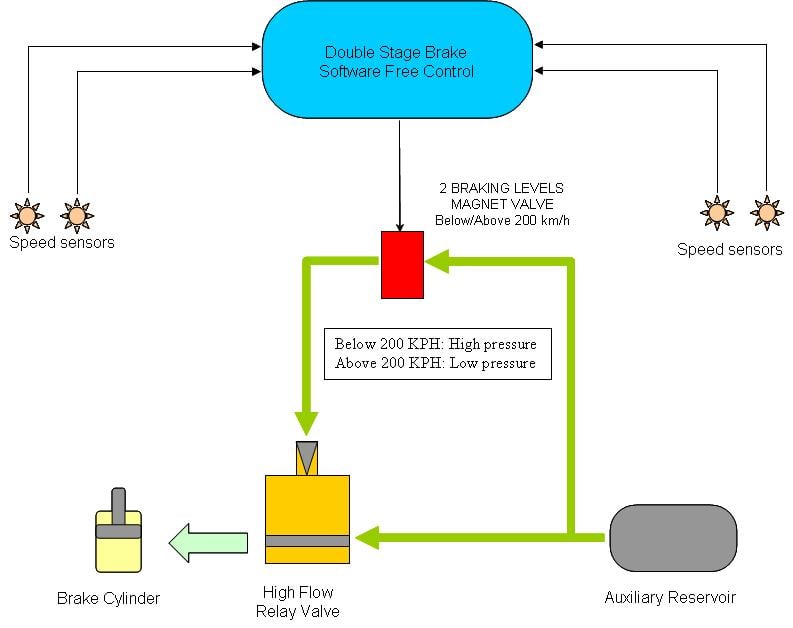
To achieve this, FAIVELEY TRANSPORT has developed a dedicated pneumatic control circuit using a magnet valve to generate two pressure signals when piloted. Although this function is implemented within the Brake Control Unit, the solution is entirely free of software intervention. Functionally it reads the axles rotation speed by means of speed sensors mounted on the bearings. The related speed signals are sent to an electronic circuit comparing them with a speed threshold value, The Magnet valve is then switched according to the speed of the train. The magnet valve can finally control the pneumatic relay valve thus generating the dual level of braking (see the diagram of “dual stage brake control”). The hardware controlled speed signal is passively monitored by the microprocessor system to check the function every time the vehicle speed threshold is crossed.
The control circuit can also set up one of these two levels as ‘default’ in case of failure of the local power supply: this ‘default’ level can then be chosen in order to give priority to the lower or to the higher pressure depending of the train operating scenario. This choice is made jointly with the car builder, the train operator and the brake system manufacturer on the basis of various requirements such as thermal capacity of disc and pad friction pair, local railway regulations and, last but not least, the achievement of the stopping distance. This solution makes the control circuit fully software independent and makes the function available with very high reliability.
Indeed, although a software implemented solution may offer more system flexibility, the reliability would make such an approach highly dependant to its level of integrity (SIL). Such a technical approach would then lead to more expensive and longer design procedures and increased impact when software changes are requested.
Moreover, in terms of accuracy, considering the speed threshold, the pure hardware control circuit is able to provide consistent values in the range of ±1 kph, especially if it includes the selection the diameter of new or worn wheel.
The solution implemented by FAIVELEY TRANSPORT is extremely flexible, because the control circuit can also be used for other functions requiring safety related digital signals depending on a speed threshold, the function can also be used in a full diagnostic information system.
The Faiveley state-of-the-art brake systems in various countries on different high-speed trains have confirmed the validity of this solution under several applications and regulations like:
• EBA approval for the Pendolino CDT680 (Czech Republic, Alstom);
• Network Rail in the UK for the new high speed train Channel Tunnel Rail Link(CTRL - Hitachi);
• Netherlands and Belgium Railway Authorities for High Speed Train V250 AnsaldoBreda.
Moreover, the discrete solution, using widely service proven and robust generations of pneumatic components has demonstrated its reliability and availability in the most critical situations that have been faced by Very High Speed train operators during the last three decades.
The definition of the adhesion coefficient versus speed is a matter of standardization in the field of the interoperability of railway rolling stock between different countries; the limit is defined as 15% for speeds up to 200 km/h linearly decreasing to 10% at 350 km/h. This means that if the train is operating at 300 km/h the brake cylinder pressure should not give a total braking force which creates an adhesion demand greater than 11.6%. Consequently, for all trains operating at a speed above 200 km/h the brake system must be able to provide levels of deceleration linked to the changing adhesion demand limit. For normal service braking this is achieved using the Brake Control Software incorporating a variable brake cylinder pressure algorithm to match the adhesion demand with the speed. For the fail-safe Emergency brake, the function is provided pneumatically and the preferred method is to provide a two stage system with a low speed and a high speed brake cylinder pressure. This dual pressure level is load weighed and independent of brake demand, it is used as the fail-safe, software independent emergency brake, the function must of course be activated automatically and safely.
To achieve this, FAIVELEY TRANSPORT has developed a dedicated pneumatic control circuit using a magnet valve to generate two pressure signals when piloted. Although this function is implemented within the Brake Control Unit, the solution is entirely free of software intervention. Functionally it reads the axles rotation speed by means of speed sensors mounted on the bearings. The related speed signals are sent to an electronic circuit comparing them with a speed threshold value, The Magnet valve is then switched according to the speed of the train. The magnet valve can finally control the pneumatic relay valve thus generating the dual level of braking (see the diagram of “dual stage brake control”). The hardware controlled speed signal is passively monitored by the microprocessor system to check the function every time the vehicle speed threshold is crossed.
The control circuit can also set up one of these two levels as ‘default’ in case of failure of the local power supply: this ‘default’ level can then be chosen in order to give priority to the lower or to the higher pressure depending of the train operating scenario. This choice is made jointly with the car builder, the train operator and the brake system manufacturer on the basis of various requirements such as thermal capacity of disc and pad friction pair, local railway regulations and, last but not least, the achievement of the stopping distance. This solution makes the control circuit fully software independent and makes the function available with very high reliability.
Indeed, although a software implemented solution may offer more system flexibility, the reliability would make such an approach highly dependant to its level of integrity (SIL). Such a technical approach would then lead to more expensive and longer design procedures and increased impact when software changes are requested.
Moreover, in terms of accuracy, considering the speed threshold, the pure hardware control circuit is able to provide consistent values in the range of ±1 kph, especially if it includes the selection the diameter of new or worn wheel.
The solution implemented by FAIVELEY TRANSPORT is extremely flexible, because the control circuit can also be used for other functions requiring safety related digital signals depending on a speed threshold, the function can also be used in a full diagnostic information system.
The Faiveley state-of-the-art brake systems in various countries on different high-speed trains have confirmed the validity of this solution under several applications and regulations like:
• EBA approval for the Pendolino CDT680 (Czech Republic, Alstom);
• Network Rail in the UK for the new high speed train Channel Tunnel Rail Link(CTRL - Hitachi);
• Netherlands and Belgium Railway Authorities for High Speed Train V250 AnsaldoBreda.
Moreover, the discrete solution, using widely service proven and robust generations of pneumatic components has demonstrated its reliability and availability in the most critical situations that have been faced by Very High Speed train operators during the last three decades.
